User Guide
Step by step: Create your first 3D scan with RecFusion.
Installation
To access the sensors the correct device drivers need to be installed for the sensors. Please also make sure to have the latest Nvidia/AMD/Intel GPU driver installed. RecFusion can be installed either before or after the driver installation.
The first time you run RecFusion the license dialog will be shown. If you have a license key enter it here to activate the software. Otherwise you can only use the evaluation version. If the PC on which you want to run RecFusion is not connected to the Internet you can also use the offline activation. Please note that your RecFusion license will be bound to the PC on which it is activated. It is not possible to use RecFusion simultaneously on multiple PCs.
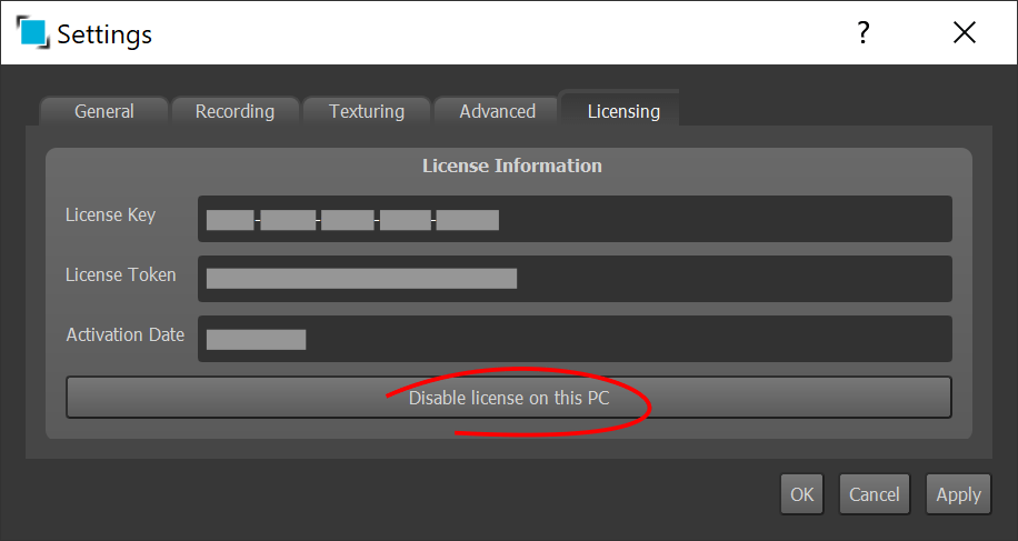
If you want to move the license to another PC, you can deactivate the license on the current PC, and perform the activation on the other.
User Interface
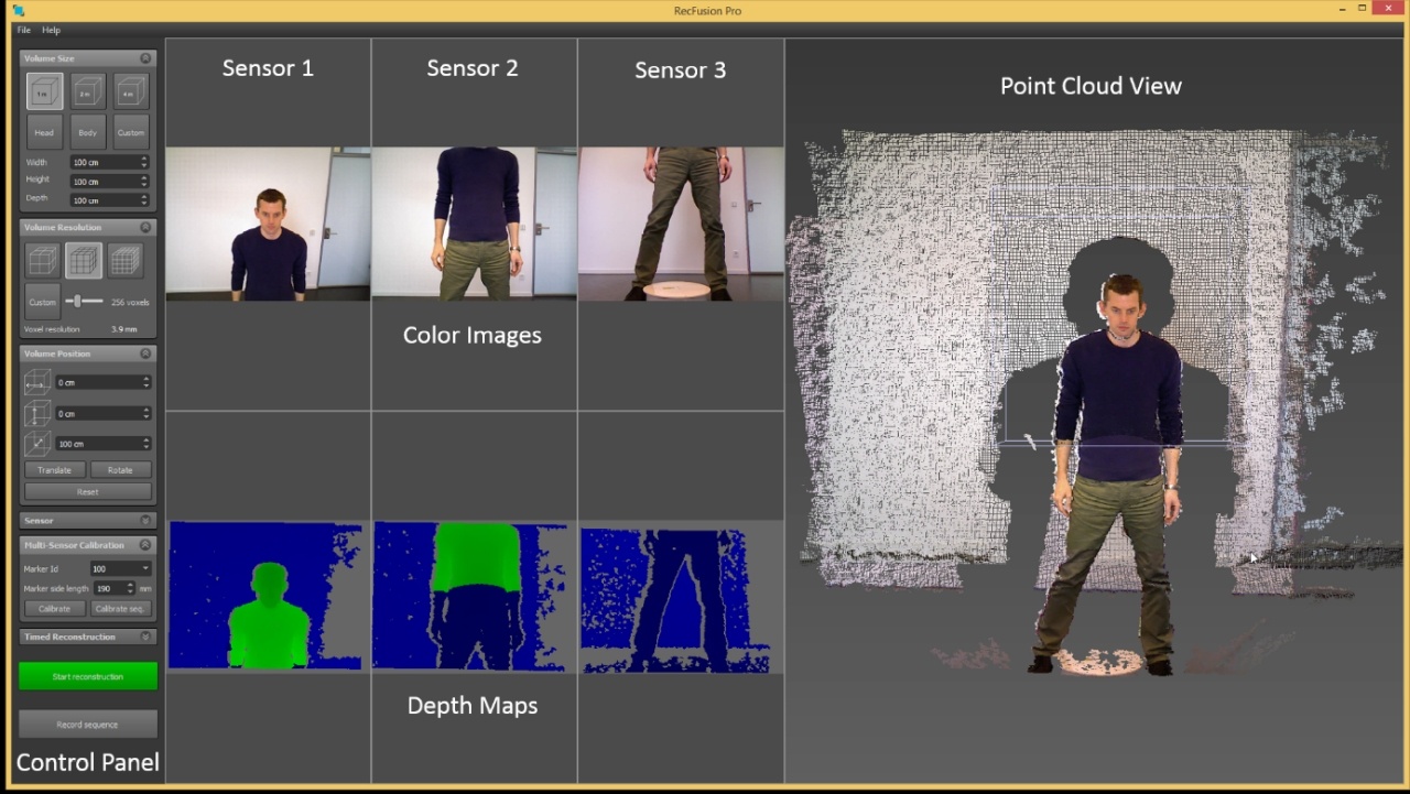
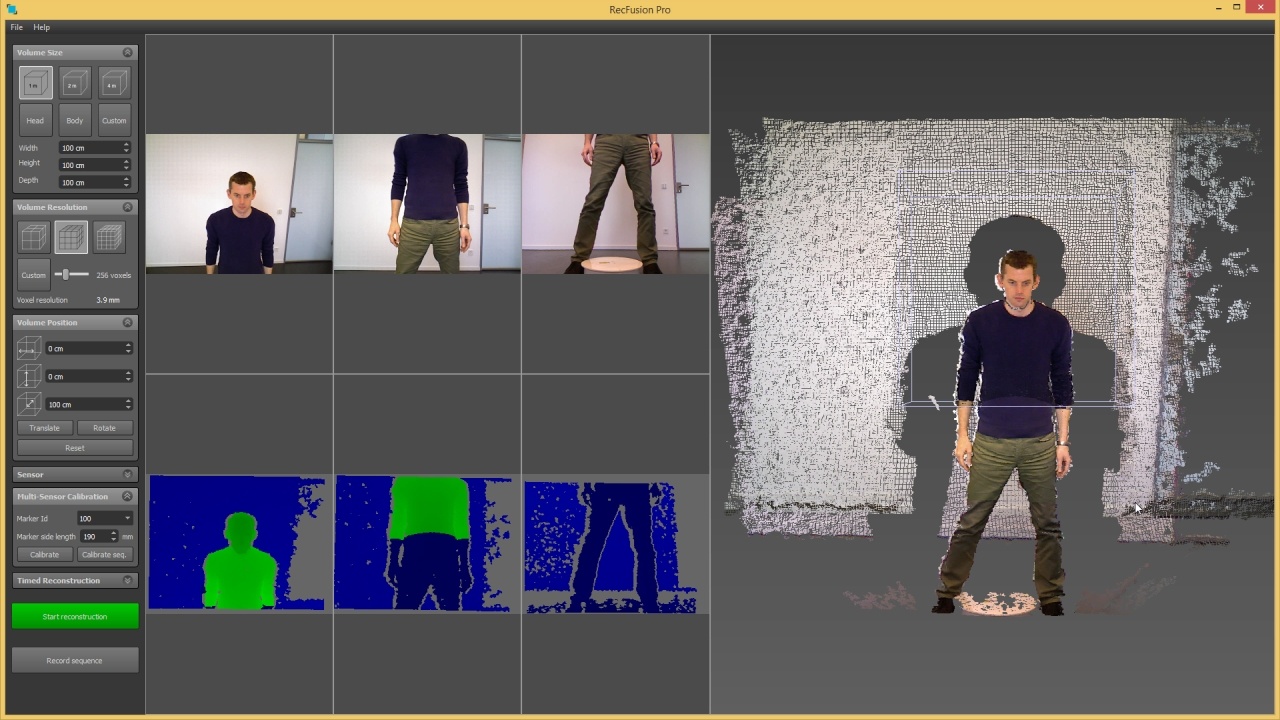
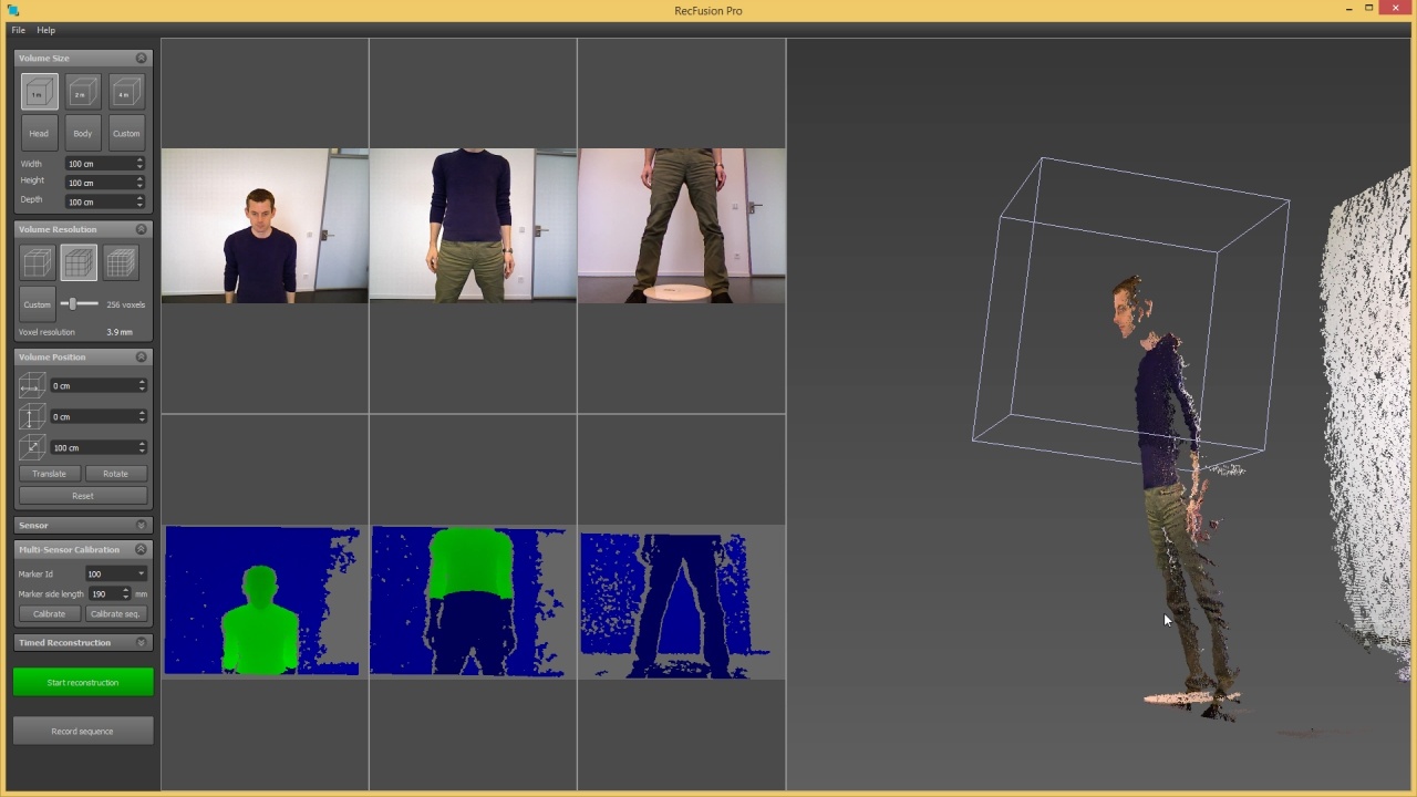
After starting RecFusion you will see the user interface shown below. It shows the color images and depth maps of the selected sensor or the loaded sequence. On the right hand side the sensor data is visualized as a 3D point cloud view. You can rotate, translate and zoom the point cloud view using the mouse. The control panel on the left side allows you to change the capture and reconstruction settings.
Sensor Selection
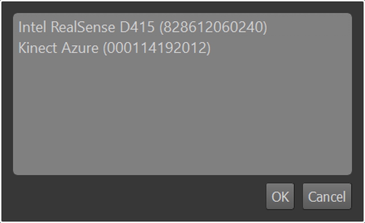
After starting RecFusion the sensor selection dialog will be shown. It lists all sensors which are connected to the PC. In RecFusion Pro select the sensors in the order in which they should be displayed in the user interface later on and click OK. After the sensors have been initialized, their images and depth maps are shown. If the order of the sensors is not as intended click on “Select sensors …” in the File menu and reselect the sensors in the correct order.
Sensor Configuration
Expand the Sensor tab on the left to view the sensor settings for the current sensor. You can change the current sensor by changing the selection in the sensor drop-down menu. For each sensor the active depth image and color image resolution and frame rate is shown. Using the orientation drop-down menu the orientation of the displayed sensor image can be matched to the physical orientation of the sensor.
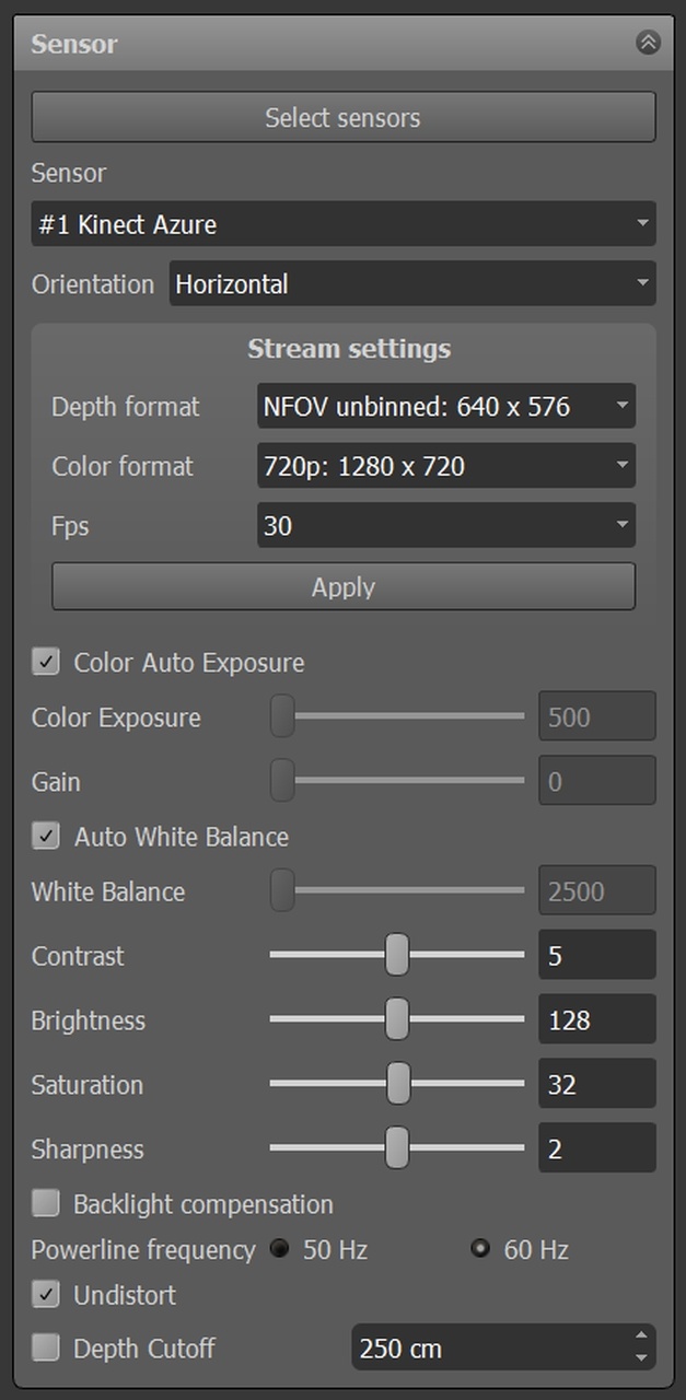
For sensors supporting those features the auto white-balance and auto-exposure settings are shown. When both, auto white-balance and auto-exposure, have been disabled it is possible to manually set the exposure time. This gives better control over the texture colors.
To remove visual clutter which is not part of the scan volume from the color, depth and point cloud views (e.g. a wall in the background) it is possible to set a depth-cutoff. Enabling this will remove all depth measurements beyond the specified depth.
Workspaces
It is a good idea to save the current settings in a workspace file using the “Save Workspace …” entry in the file menu. The saved workspace file contains all sensor settings including the sensor order. When loaded again it will restore all settings. Double-clicking on the workspace file will open it directly in RecFusion, so it is a good idea to place it in a location where it can be conveniently accessed, e.g. on the desktop.
Multi-Sensor Calibration (RecFusion Pro only)
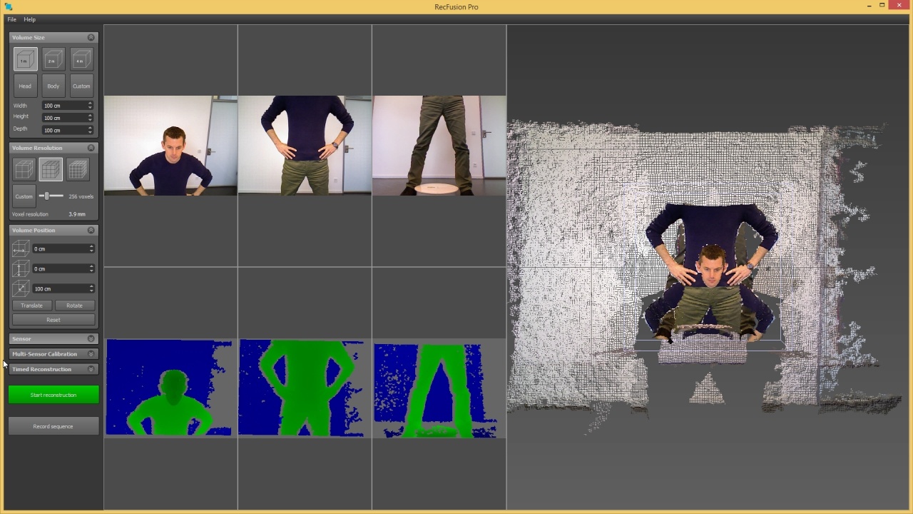
Before calibrating the sensors the point clouds in the point cloud view are not aligned (see Fig. 8). To align the point clouds the sensors must be calibrated, i.e. their relative positions must be determined. To calibrate the sensors a calibration pattern needs to be used. Using the known structure of the pattern RecFusion Pro can determine the position of the sensors with respect to each other.
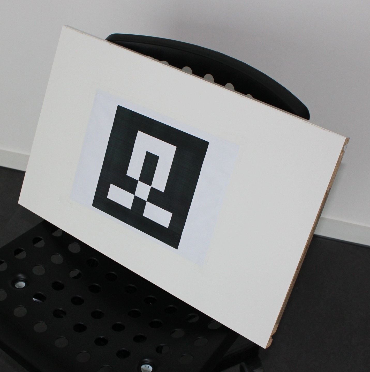
The calibration pattern can be accessed from the RecFusion Pro start menu entry (Start Menu -> RecFusion Pro -> Calibration Pattern). When printing the pattern any scaling to fit the page size needs to be disabled. The side length of the printed pattern must be 190 mm. It must be placed on a rigid and flat surface, e.g. a wooden board (see Fig. 5). The pattern should not bent or be distorted in any way.
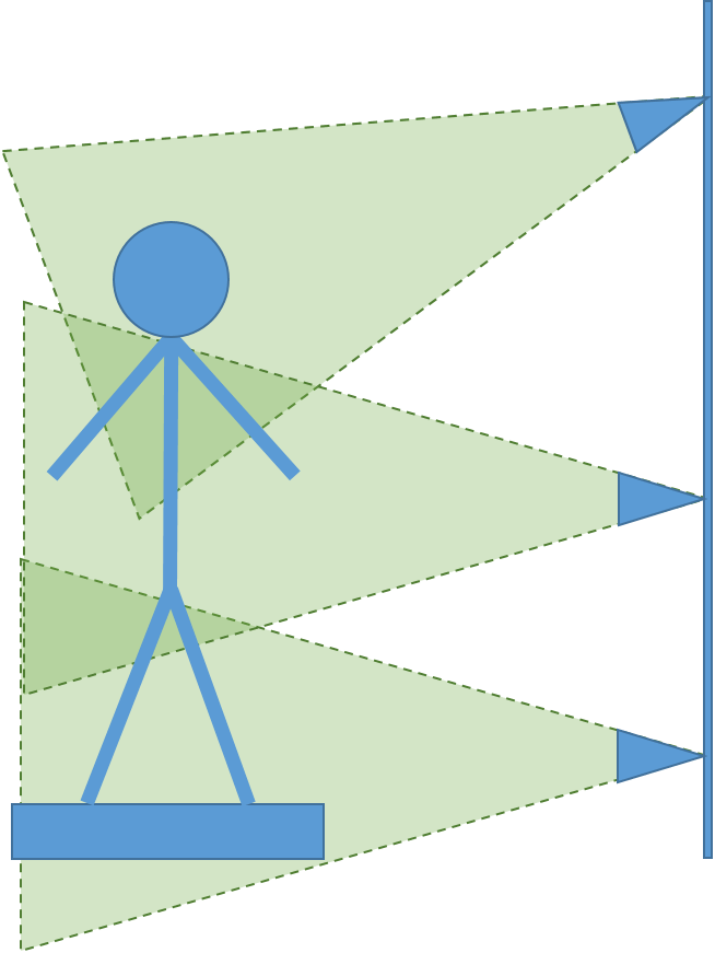
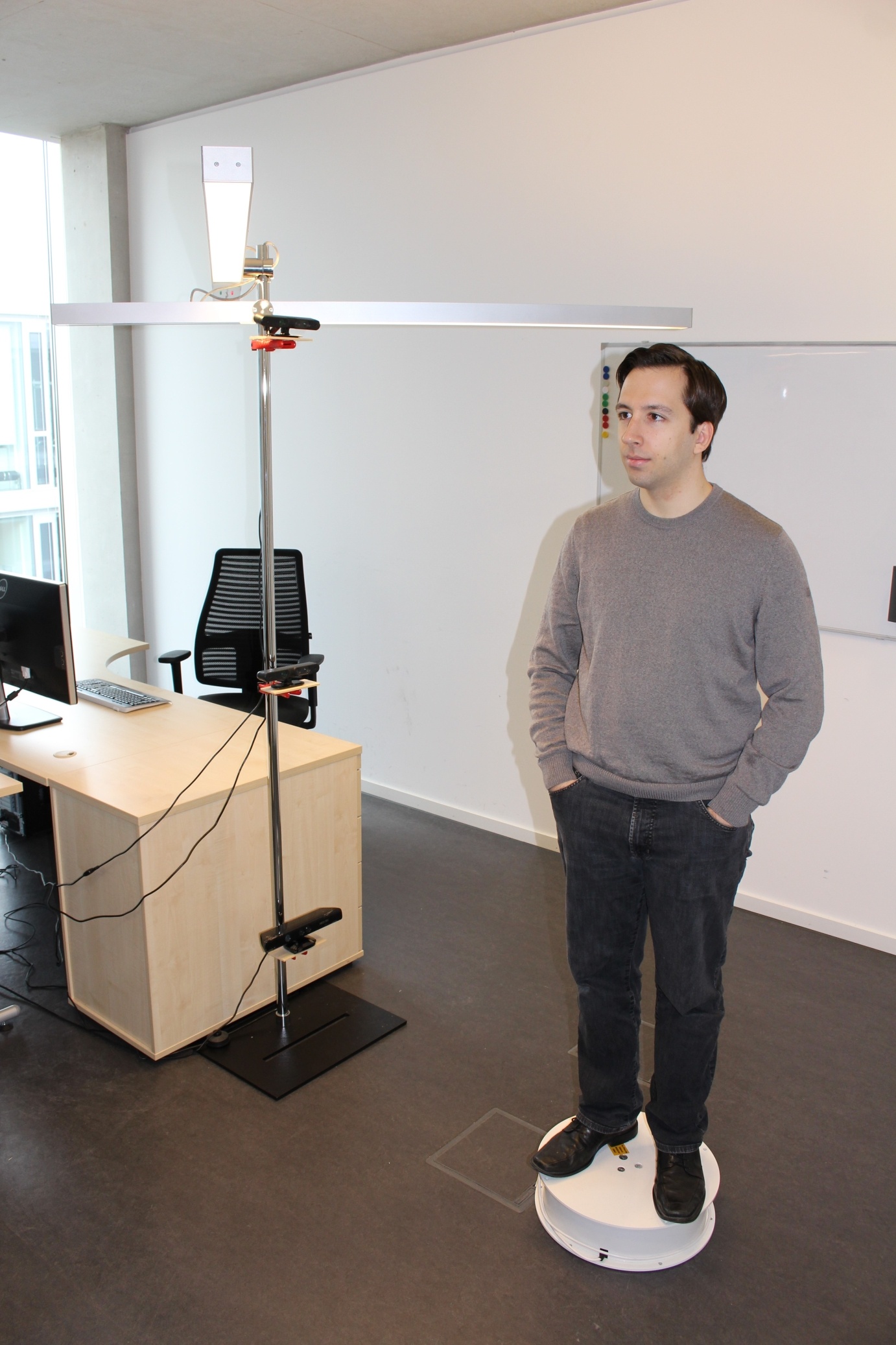
To calibrate the sensors, set the pattern number and the pattern size in the multi-sensor calibration tab. The default settings fit the standard pattern linked in the start menu. There are two calibration procedures provided with RecFusion Pro which are designed to allow calibrating all kinds of multi-sensor setups provided that there is at least some overlap between some of the sensors. The first method requires the calibration pattern to be positioned in such a way that it can be seen by all sensors at the same time while the second method (sequential calibration) only requires the pattern to be visible in two consecutive sensors (as defined by the order in which they are shown in the user interface). The sequential calibration is particularly useful for sensor setups in which the sensors are placed in vertical order (see Fig. 6 and Fig. 7).
After clicking on “Calibrate” or “Calibrate Seq.” depending on which calibration method you want to use, an image for each sensor will be acquired and used for calibration. It is important, that the calibration pattern is not moved during this time.
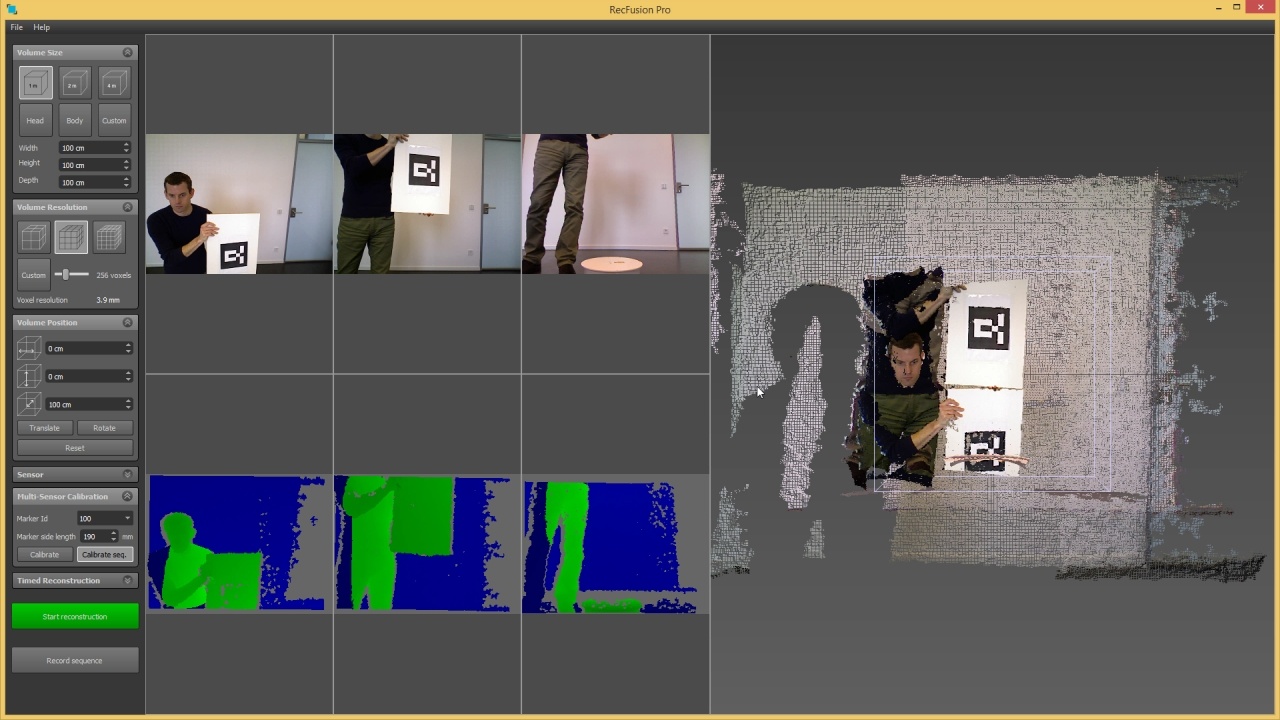
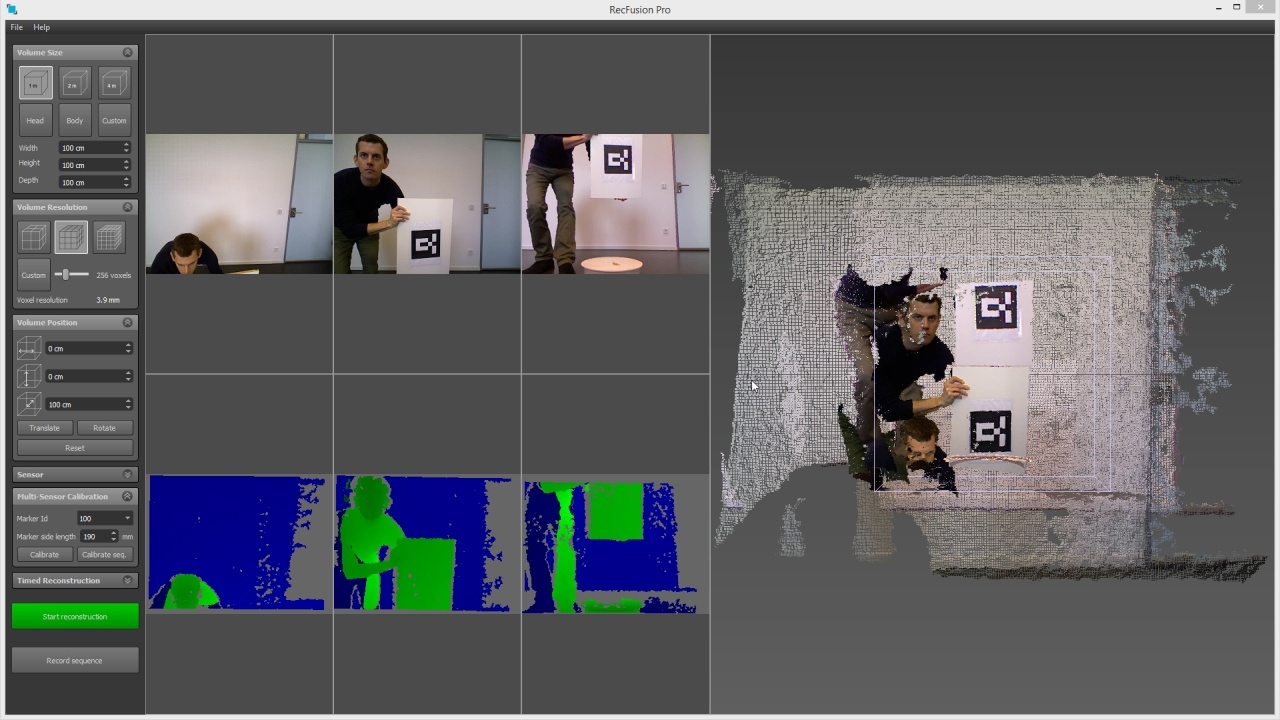
For the standard calibration the pattern needs to be placed so that it is seen well by all sensors while for the sequential calibration it first needs to be seen by the first and second sensors (see Fig. 9). It is important that the pattern is as large as possible in all sensor images. The pattern should also not be placed too close to the image border. For the sequential calibration a message will be displayed after detection of the pattern in the first sensor pair asking for the pattern to be moved so that it is visible in the second and third sensors (see Fig. 10). This will be repeated until the pattern has been seen by all consecutive sensor pairs.
If the calibration succeeded a success message will be displayed. If the calibration pattern was very small in the image, the calibration might be inaccurate. In this case the calibration pattern should be moved closer to the sensors if possible or printed on larger paper (e.g. on DIN A2 paper). When printing out a larger version of the pattern the calibration pattern side length in the multi-sensor tab needs to be adjusted accordingly. After a successful calibration the point clouds in the point cloud view on the right are aligned (see Fig. 11 and Fig. 12). The point cloud view should be carefully examined to make sure that there are no misalignments.
Saving a workspace for a calibrated setup will also include the calibration information so that the next time the workspace is loaded the calibration is already correct. Please note that the calibration stays only valid if the sensors don’t move. If the sensors are moved, the system needs to be recalibrated.
Reconstruction Settings
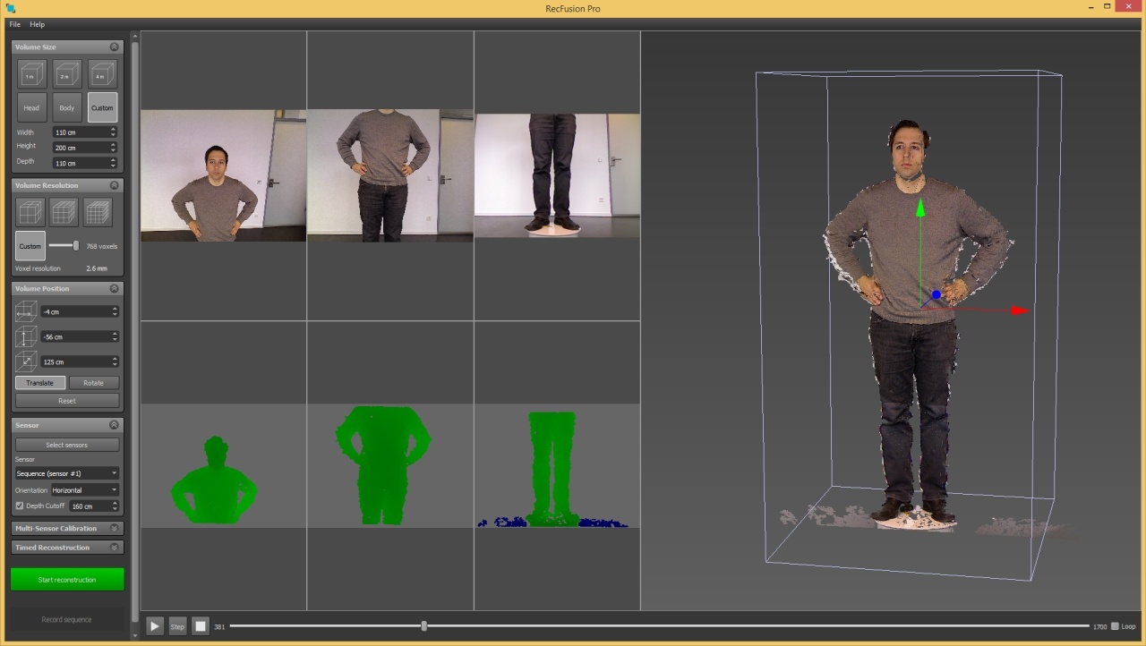
Before beginning a scan, the reconstruction volume needs to be defined. The scan will contain all objects which are located within this reconstruction volume. The volume is visualized through the box shown in the point cloud view. For better visualization everything located inside the cube is also colored green in the depth map view of each sensor. The volume needs to be adjusted in size and position to contain all objects which are to be reconstructed. When reconstructing objects on a rotating on a turntable it is important not to select any not-rotating parts of the scene such as walls or the floor, but only the object on the turntable (see Fig. 13).
The size and the location of the reconstruction volume can be modified by several means. The size of the volume can be changed through the Volume Size tab. Alternatively it can be changed by clicking and dragging the middle mouse button vertically in the depth view of any sensor. This will scale the reconstruction box.
The location of the volume can either be changed by setting the position values in the Volume Position tab or by clicking on the Translate button and dragging the axes handles which are then shown in the point cloud view (see Fig. 13). Another option for moving the volume position is to click and drag in the depth view with the left or right mouse button.
Next, the volume resolution needs to be defined. It should be set so that the voxel size displayed in the Volume resolution tab is less than 1.5 mm. For live reconstruction please consider that the higher the resolution is, the more processing power is needed. If the framerate during reconstruction is too low (i.e. too many frames have to be dropped) consider using a lower resolution. For offline reconstruction this is not an issue. The maximum achievable resolution is limited by the available GPU memory. If there is insufficient memory for the chosen resolution RecFusion Pro will give a warning. Please choose a lower resolution in this case.
It is optionally possible to set a start delay before the reconstruction starts. This can be done through the Timed Reconstruction tab. On the same tab it is also possible to set a fixed time after which the reconstruction stops, e.g. the time of one turntable rotation.
When saving a workspace all volume settings will be recorded, too. The next time the workspace is loaded all settings will be automatically applied.
Live Reconstruction
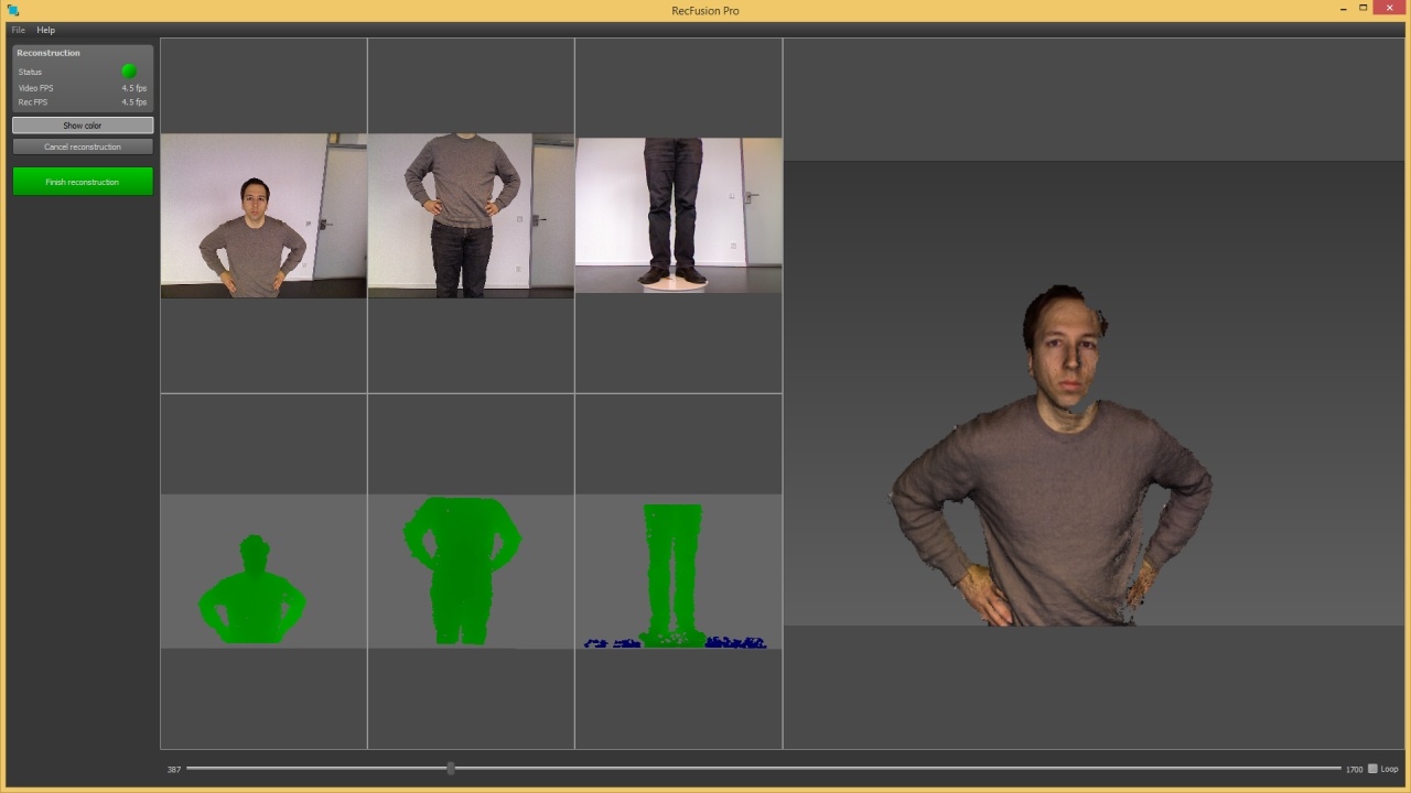
Once the reconstruction volume has been defined, the scan can be started by clicking on Reconstruct. During the scan the reconstruction view is shown (see Fig. 15). Instead of the 3D point cloud view a live view of the current reconstruction result is shown on the right. Using the Show Colors button on the left it is possible switch between a colored and an uncolored view of the current reconstruction.
The status indicator on the top left shows the state of the scan. If everything is working fine, it will be green. If it is red, an error has occurred. Typical error sources are a too fast movement of the sensor or leaving the reconstruction volume. During the scan the frame rate of the sensor and of the reconstruction are shown in the left panel. The reconstruction frame rate should be larger than 10 fps for the scan to work properly in live mode. The lower the frame rate the slower the sensor movement needs to be, since otherwise tracking might be lost resulting in a red status indicator. The achievable reconstruction frame rate depends on the volume resolution and on the GPU. To obtain higher frame rates the volume resolution can be reduced. Clicking on Finish Reconstruction finishes the scan.
Sequences and Offline Reconstruction
Clicking on Save Sequence in the capture view allows to record the sensor streams in a space-efficient format. Recorded sequences can later be reloaded using the Load Sequence File menu entry. When a sequence is loaded playback controls will be shown below the sensor views. To reconstruct from a sequence the volume settings can be made just as in live mode. The reconstruction will start from the currently selected frame in the sequence. Therefore the volume should be defined on this frame. The reconstruction ends when either the end of the sequence is reached or Finish Reconstruction is pressed. For multi-sensor sequences the data is recorded to memory by default since the data rate of multiple sensors is too high for normal hard drives to handle. The maximum amount of memory to use for recording sequences is determined automatically. Alternatively it can be manually set from the settings dialog in the File menu. After the recording has finished the data is compressed and written to disk.
Post-Processing
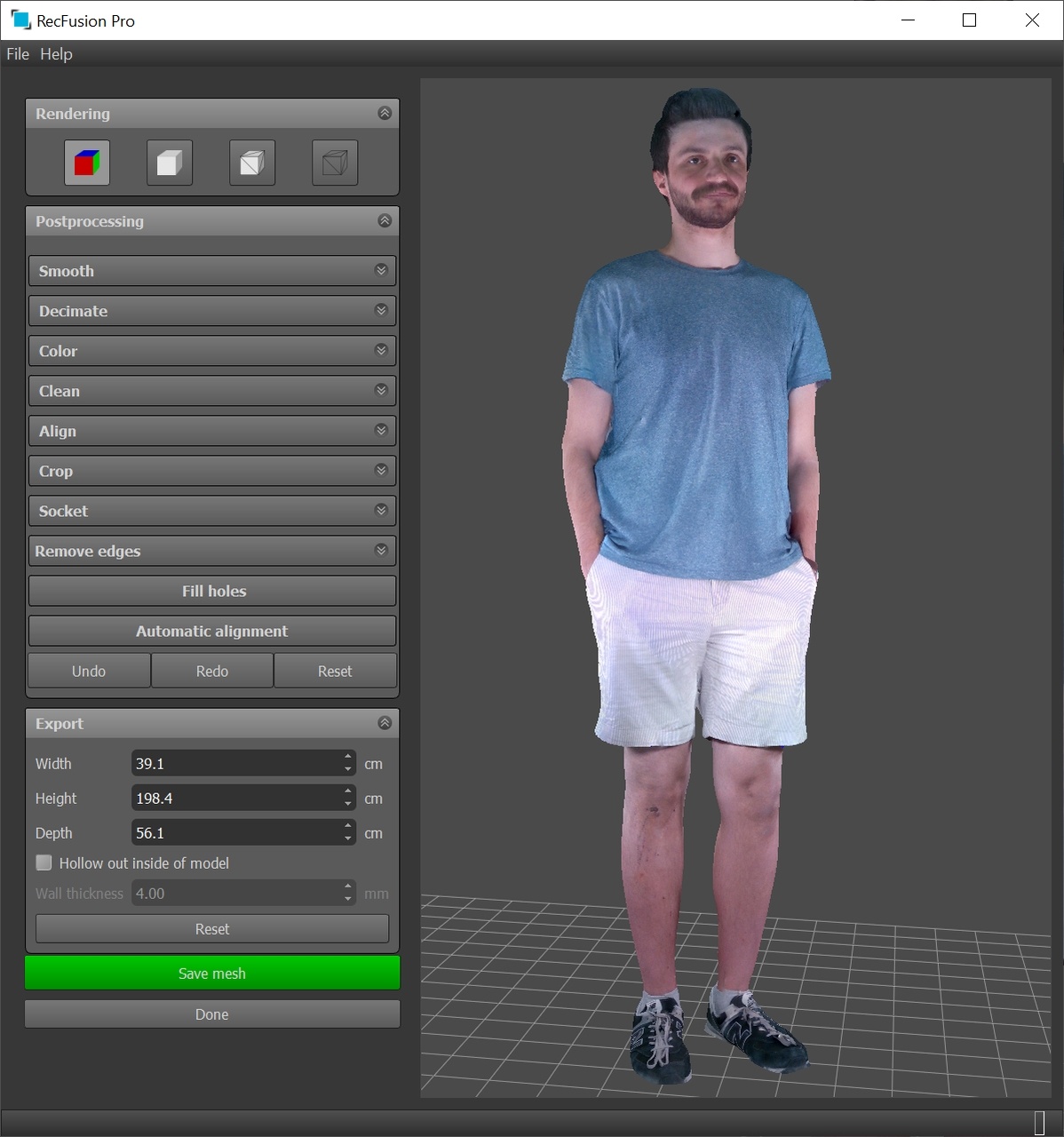
After the reconstruction has finished the post-processing view will be shown (see Fig. 16) which allows to view the model with and without texture, to edit it and to save it.
The following post-processing functions are available.
Smooth – Smooth the model using the given number of iterations.
Decimate – Decimates the number of triangles so that the maximum edge triangle edge length is given by the specified number. By default the subdivision amount is based on the surface color variation to retain the colors. This can be disabled by unchecking the preserve colors checkbox.
Color – Allows to adjust brightness, contrast and gamma of the mesh colors
Clean – Removes disconnected parts of the object based on their surface area. All parts larger than the minimum size and smaller than the maximum size will be removed. Parts which will be removed are displayed in red.
Crop – Removes all parts of the model outside the shown bounding box (colored red). The cropping volume can be adjusted by moving, rotating and scaling the bounding box.
Align – Rotates the model, for instance to align it with the ground plane.
Socket – Adds a socket to the model. The diameter, the height and the color of the socket can be specified. The socket can be moved by using the manipulator in the 3D view. Clicking on Remove removes the socket.
Remove edges – Removes border triangles from the mesh.
Fill holes – Fills all holes in the model to obtain a watertight mesh. This is required for 3D printing.
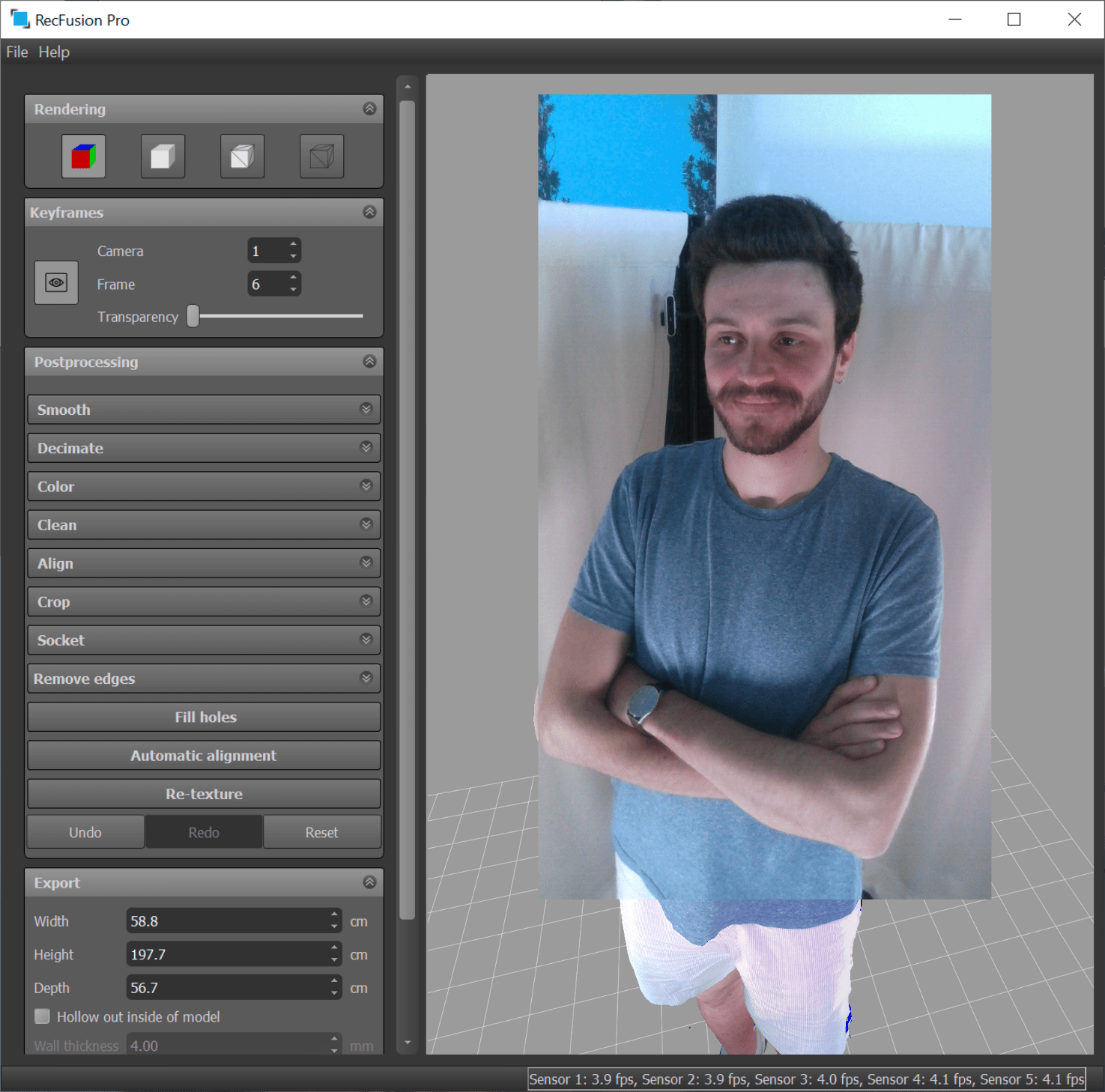
Re-texture – Applies texture mapping from acquired keyframes to the mesh. This functionality allows to create more photo-realistic meshes (see Fig. 17).
Keyframe preview
A user can view the frames that are saved during the reconstruction and which can be used for mesh texturing.
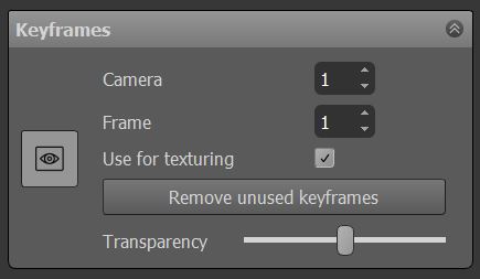
These keyframes will be visualized as an overlay images on top of the mesh. You can select camera and particular frame number. Transparency scroll bar allows to change the transparency of the overlayed image.
If some keyframes are blurry or misaligned, a user can choose not to use these particular frames for the mesh texturing. Check box “Use for texturing” should be used for specifying such frames. The button “Remove unused keyframes” can be used to completely remove the unused keyframes.
Project Export
The model together with its keyframes can be saved by clicking on “Save Project…” in the File Menu. This allows to perform keyframe selection and mesh texturing at a later point of time.
Mesh Export
The model can be saved by clicking on Save Mesh. The supported mesh formats are STL, OBJ, PLY and VRML. In the Export settings the desired dimensions of the exported model can be specified. Optionally the model can be made hollow using the specified wall thickness. This allows to reduce the material cost for certain 3D-printing methods. All export functions are disabled in the evaluation version.
For questions and feedback you can use the RecFusion forum
Table of Contents
Recommended Tutorials
RESOURCES & SKILLS
Expand your skills
Our resources and tools are designed to help you grow and develop your skills.
User Guide
Explore RecFusion workflow and follow the recommended practices to achieve the best scanning results
Forum
Get expert tips on 3d scanning, post your questions and get advices from other RecFusion users

